BurgerTime High Score/Free Play Upgrade
So, the BurgerTime free play/high score save kit upgrade didn’t exactly go as planned. As noted in that entry, the installation kit requires the replacement of the static RAM chip at location 14D on the main board. Unfortunately, the 24 pin RAM chip is soldered to the game board, requiring it to be desoldered and a 24 pin socket resoldered in its place to house a Non-Volatile RAM (NVRAM) replacement chip that will maintain the high score table, thus saving the high scores between playing sessions. Unfortunately, my soldering skills are not as refined as they apparently need to be and the system did not come up properly after the socket installation and NVRAM chip install.
Looking back now, I probably should have verified the continuity of all 24 pins of the newly soldered RAM socket before I attempted to re-power the unit after installation. I’m hopeful that any errors in continuity did not do further damage to the game board or installed ICs.
After consulting the BurgerTime schematic diagram, I mapped all locations that each of the 24 pins of the RAM chip connect to. Then, using the continuity setting on my Fluke 115 multimeter, tested each connection.
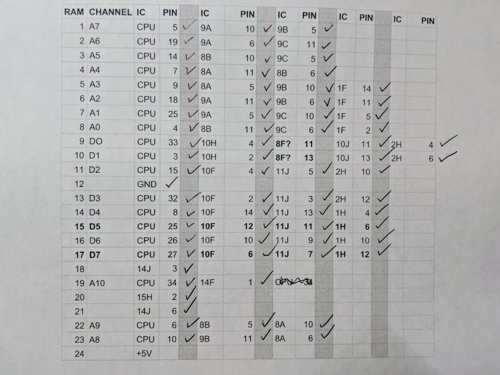
The first time I went through, all connections were solid except for RAM pins 15 and 17, which connected via data bus channels D5 and D7 to CPU pins 25 and 27 respectively. I tried to resolder those pins on the RAM socket but simply could not get a clean connection. I double checked the schematic to make sure I was reading the connections correctly and they seemed right.
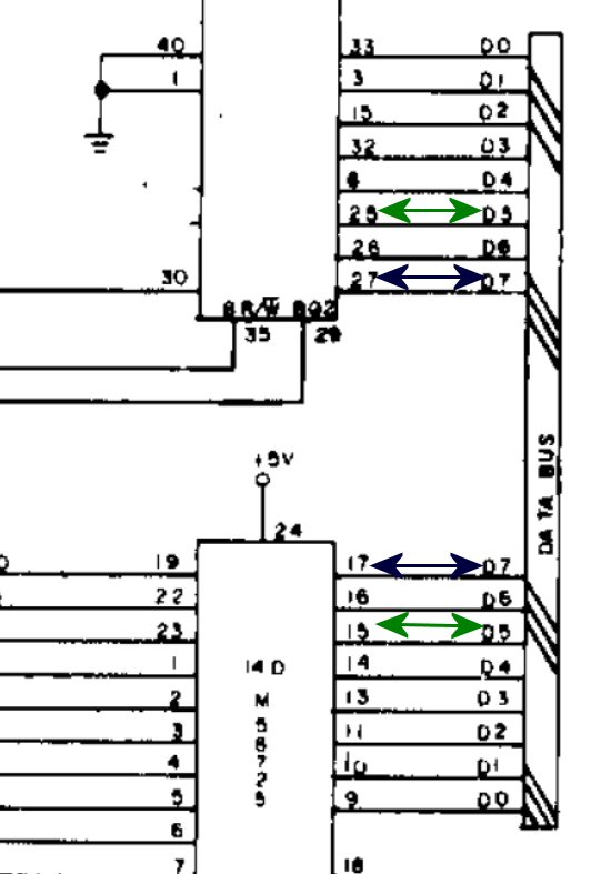
Perhaps the data bus traces became compromised when the soldering was done. I decided to simply jumper the pins between the two chips to establish the connectivity needed.
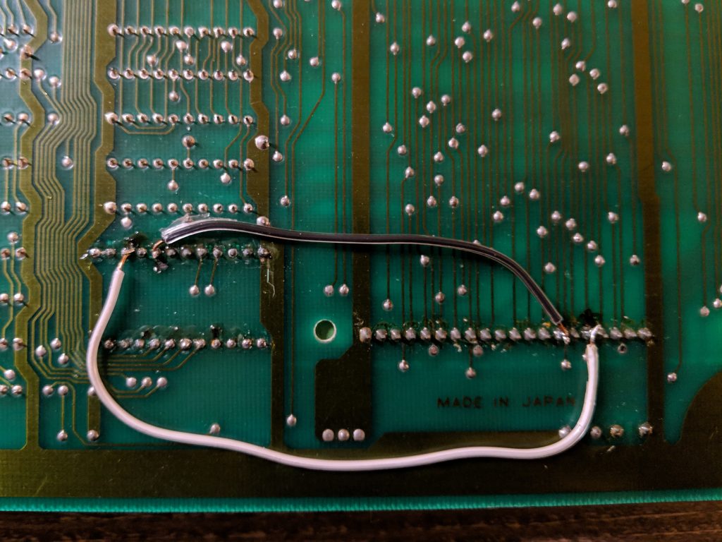
Unfortunately, this did not fix the problem. After this patch, I did get a garbled screen image, so there was a slight improvement but no fix to the game play. Perhaps I did blow something up when initially powering the game with RAM pins 15 and 17 not properly connected?
I retested all lines and everything checks out except for connections that appear to be noted for the D0 and D1 data bus channels between RAM pins 9 and 10 to an IC at location that looks like 8F.
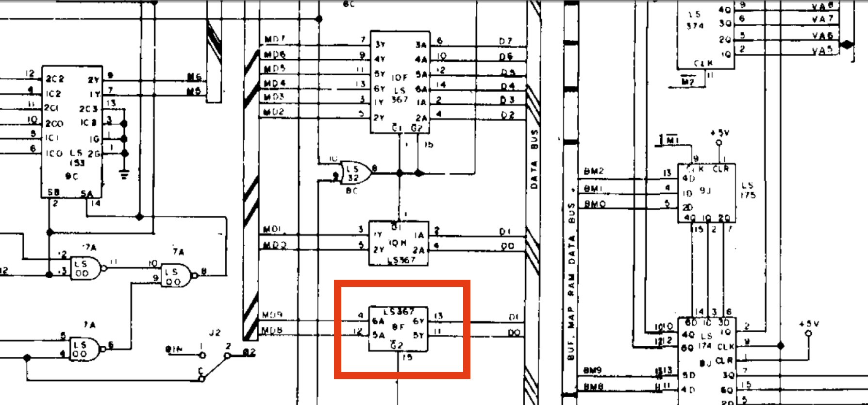
It’s hard to make out definitively from the schematic if this is IC position 8F. I have checked two different schematic scans and by all estimations, this appears to be correct. The problem is, on my game board, there is no IC at position 8F.
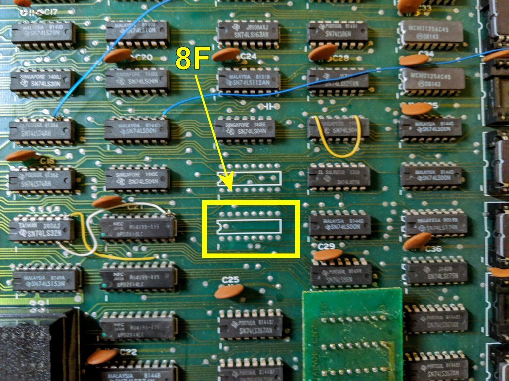
I did test the empty pins for continuity (there was none), but the fact that there is no IC (denoted in the schematics as an LS367 — same as the chip above it at 10H which IS there and properly connected to data channels D0 and D1 as denoted in the schematic) leads me to believe that either I am mistaken about the IC position because it is hard to read OR the board has been modified in some way. I’m hoping it is the former, but I am at a loss to determine the correct IC position and whether or not this is actually the problem I am having.
I decided to post the issue to the KLOV/VAPS discussion board.